Modifications for the Kenwood
TM-732
Picture

19-07-1998 AIR CLONING (Does not work in K1
or E1 Mod modes)
This procedure allows you to clone a second
transciever as above, over the air. The data is transmitted automatically using
DTMF tones. During transmission (which is one-way only), the master will
automatically switch to LOW power. To be legal, use only a UHF cloning
frequency.
This procedure is not enabled in the stock transciever. At a
minimum, you must cut the green wire to make iwork.
- Configure master transciever's memories as desired. Select UHF simplex
transmit frequency and set PTT to UF H(will work on VHF but is not
recommended).
- Switch the power OFF. Press and hold the CALL and DTSS tutons and turn the
power back ON. "CLonE" appears in display.
- Set the receive frequency on the slave transciever the same as that of the
master. Turn power off, hold down call and dtss keys and turn power on.
'clone' appears in display.
- Press the ptt on the master's microphone. Data transmission will begin. In
case of a receive error, the slave transciever will display 'err'. when the
prcedureo is complete, both radios will display 'end'.

19-07-1998 PAGING ANSWERBACK (Does not work
in K1 or E1 Mod modes)
The exact operation of this feature is
unclear but the folling description has been given:
- To enable, hold down the F key and press the TONE key.
- Do disable, repeat step 1
When enabled, documentation says: "If a
maching code is received and the other transciever is no longer BUSY, the code
of the local transciever is sent to the other transciever. The answerback
function then turns off."

19-07-1998 Memory
recovery
(requires DTMF microphone)
(Documentation of this
"feature" is diffiult to comprehend but perhaps someone will figure out what it
does.. I suspect that "RECOVERY" refers to returning the memories to their
original state after changing the split memory layout.)
- Hold down F and C.SEL, turn on power
- Press D, followed by 7 on the microphone. "Inspection Mode" is now
enabled.
- To cancel, press and hold F and then C.SEL
"Note:
Before
recovery, the memory channels must be returned to the previous state (number of
split memories, etc.)."

19-07-1998 Subjective
Impressions
Being a TM-741 owner, there were a couple of things
that I mied on the 732. First, there's no real-time clock, no sleep timer, no
programmable ON time/ OFF time feature. There is an APO (automatic power off)
with a preset time of 2:59:00 of inactivity until power down.
Another
complaint is the slow scanning speed. The unit will scan VFO or memory at no
more than about 5 channels/frequencies per second per band. I consider this to
be terribly slow in today's age. The slowness is probably due to the fact that
the remote contains all of the scanning logic and because the data path between
the head and the base is over a 2 wire serial data stream.
Anotherp
erennial complaint is that the radio does not cover the entire UHF frequency
band of 420-450 Mhz. As shipped, the unit will only operate over the range from
438 to 450, (transmit or receive) which I find objectionable.
The manual
is of typical quality and fairly complete although not well indexed. There are
so many functions that a cheat sheet is needed but as mentioned, was sadly not
included. In typical fashion I note that the Japanese have never been able to
adequately and clearly explain how DTMF Squelch and Paging works. They've tried
diagrams and jinglish explanations but in the end you still end up reading the
instructions over and over before you fully understand them. I'd love to see a
plain English discussion of how the DTMF features are intended to work and how
they really work in practice. Fllow that with a step by step example and we'd
probably have something that could be more popular.
One of my reasons for
buying the radio was to use the remote mounted head option. The option, the
PG-4K kit, is advertised as a 13 foot extension. What you don't find out until
you buy it, however, is that only the display cable is 13 feet long and the
microphone cable is only half that! To me this meant that although the display
cable would let me trunk mount the base, there was no way I could get by with a
6 foot microphone cable. The solution: buy the PG-4M(?) which is the longer
model for another $30! Needless to say, I'm not a happy camper! Are you
listening Kenwood????
On a positive note about the remote cabling, at
least with the 732 it is possible to roll your own. The 4 conductor head to
chassis connector cable could be easily spliced and extended, and an ordinary
RJ-45 extension cable could be used for the microphone. For many folks, however,
it's probably easier to just buy the short ($47) or the long ($78) cable
kit.
The extension cable issue aside however, it still looks like it will
be a very good radio. As always, after spending a big wad of cash I'm
automatically inclined to say that I like the radio. This is no exception, the
TM-732 does a fine job at heading off the competition at a good
price-performance point.
The price is the same as the older TM-731 which was
around $650 retail (real price, not the bogus MSRP).
To conclude, I think
Kenwood has come up with a fine replacement for the 731, and has put a lot of
thought put into the design of the 732.
Operating
Features
Kenwood has done a fairly good job at maintaining a
consistent user interface between their models. Being familiar with the 241 and
741, I found it pretty intuitive to operate. Not intuitive enough, however, to
venture out of the house without taking the operators manual along since they
sadly omitted a quick reference card (like the give out with the 741). Unless
otherwise noted, the 732 generally has the same basic feature set as the TM-241
plus several extras.
The following is an unordered list of outstanding
bits of trivia regarding the 732's features:
1. Dual In-Band Receive:
Competitive pressures (e.g. Icom's 2410) has now made this a standard. You can
set the display to receive any combination of: VHF/UHF, VHF/VHF or UHF/UHF. This
capability is quite well engineered and makes it possible to transmit as well as
receive on either band's second display. It is not possible (understandably) to
have a full duplex QSO on an in-band setup. In other words, when you set the
radio to monitor two UHF or two VHF frequencies, one of these frequencies is
muted when you transmit on the other. This is not so when the selection is
VHF/UHF, where the receiving band is not mut during transmit.
Looking at
the schematic, the dual in-band receive is well implemented with each of the
transceiver boards having two receiver front end units (RF amp and mixers), one
for each band. There are some unsymmetrical aspects to the dual in-band receive.
First, the UHF receiver does not have an AM mode which means that you cannot
monitor AM aircraft spectrum at 118-136 MHz with the UHF receiver. Similarly,
you cannot monitor 800 MHz with the VHF receiver. Each of these modes AM
aircraft and 800 MHz, are unique to the VHF and UHF receivers
respetively.
A nice touch is that even though the second receiver is
utilized on the other band, the transmitter is automatically switched back to
the proper band which allows you to transmit on either of the two frequencies
while using the dual in-band mode.
2. Smart Mute: The MUTE function is
now intelligent in that it mutes the non-PTT band only when necessary. This
means that the audio muting (actually, 20Db of audio attenationu) is switched
into the auxiliary band only when something i being received on the primary
band. Previous Kenwood rigs muted the auxiliary band at all times when the MUTE
function was active.
3. More programmable microphone function keys:
Previous Kenwoods allowed you to program the PF mcrophone key only.
With the
732, you may program any of ttop 4 function keys (CALL, VFO, MR and PF), even
for example, with such multi-key sequences as [F][VFO].
4. New Display
Lighting: The display is the now-standard black letters on a light background.
Like the 741, it has 4 light levels, plus OFF (no light) which is interesting.
Also, there's a special feature which when enabled mkes the display jump up to
the next brighter display level whenever a button or key is pressed, returning
to the dim level after 5 seconds of inactivity. When used with the OFF level it
gives you a display which is completely dark at night and comes on only when you
need it. There is, however, a small green LED off of the display which remains
lit at all times to show which band is in use.
5. Memory: As advertised
the radio comes with 25 full-however, is that you can have up to 64 memories if
you are wiling to forgo the odd-offset capability to varying degrees. For
example, if you can live with only 5 odd-offsets then you'll get 30 memories per
band. If you don't need any odd-offsets then you get 32 memories per band. In
addition, you can apportion the 64 available slots between the two bands in
whatever ratio that you desire (in 5 channel increments). In other words, you
can configure for 50 UHF memories and 14 VHF memories if you like.
M  22 21 20 19    VHF      UHF    SHIFT    800     REMARKS

K1  0  1  0  1  144-148  438-450  .6/5          STD. US VERSION
K2  1  1  0  1  144-148  438-450  .6/5      X   US AFTER GREEN WIRE
CUT
K3  1  0  0  1 142-152  420-450  .6/5      XF   MARS/CAP MOD
K4  0  1  1  0 136-174  410-470  .6/5      X   ALL BAND MOD
M1  0  0  0  0  144-148  430-440  .6/5          GENERIC INT'L MODEL
M2  0  1  0  0 136-174  410-470  .6/5      X   ALL BAND INT'L (430
DEFAULT)
E1  0  0  1  0 144-146  430-440  .6/(1.6)      STD EUROPE MODEL
E2  1  0  1  0 136-174  432-438  .6/1.6    X   DENMARK
E3  0  0  1  1 144-146  410-470  .6/(1.6)  X
E4  1  1  0  0 144-146  430-440  .6/(1.6)  X
E5  1  0  1  1 136-174  410-470  .6/(1.6)  X   EUROPE ALL BAND
C1  0  0  0  1 136-174  340-512  5.7/10        CHINA MODEL

0 = RESISTOR IN     1 = RESISTOR OUT
Notes:
- All 'resistors' o ohms (wire jumper ok)
- Green wire is equivalent to R22 - present in K1 model Press ENTER to
continue (A to abort) -->
- 0 = RESISTOR PRESENT, 1 = RESISTOR ABSENT
- Standard shifts in MHz VHF/UHF. those listed as (1.6) also DO -7.6
- Codes not listed are used in japan version, special cpu required
- M Column is factory mode number
- K2 mod includes 410-770 receive and enables cloning feature to perform any
of these mods, remove the back cover from the remote head unit. Resistor
numbers clearly marked on board along top.

19-07-1998 800 MHZ RECEIVE
To
enable 800 receive, switch to uhf vfo (not available in uxu), press and hold mhz
button until 800.000 appears.
A capacitor must be added (c348) to enable
the 800 receiver.
to add, remove uhf transciever board and next to the pad of
n 1 of ic-202 (on the foil side), add a 2.2 pf chip capacitor.
a wire can be
used instead of the capacitor but sensitivity will be reduced. (see schematic
diagram for reason).

19-07-1998 Hard-wire
cloning
(works in all confguration modes)
This procedure
allows you to clone the entire memory of a 'maer' transciever into the memory of
a 'slave' transciever.
First, construct an rj-45 jumper cable as
follows:
------!                           !------
   UP ----------------------------- UP       Note that ptt and down
    E ----------------------------- E         are crossed end-to-end
  PTT ----------------------------- DOWN
 DOWN ----------------------------- PTT
------!                           !------
For hacker's reference: UP=CLK, PTT=SO/, DOWN=SI
- Configure the master transciever's memories as desired.
- Switch power off, hold down f and mhz keys and switch power back on while
holding keys. Display wi show 'clone'.
- Set the slave transciever in the clone mode (as in step 2).
- Plug the cable into the two radios (which end doesot matter).
- Press the call button on the master. When 'end' is displayed, operation is
complete.

19-07-1998 TM-732E fuer
9600
Hallo, habe meinen Kenwood TM-732E erfolgreich umgebaut auf
9600Baud.
NF Ausgang zum TNC an TX-RX UNIT/430 MHz an IC201 (KCDO4) Pin
12 Signal DET.
NF Eingang vom TNC an TX-RX UNIT/430 MHz an Leitung R257
nach VR202 Sig.
MAX DEV.
PTT an Microfonbuche gegen
Masse.
Fragen Ueber Box DB0IZ oder Digi DB0END in 1200Baud oder
0202/521349.
73 55 Joerg aus Wuppertal DD8JM.

19-07-1998 TM-732 gets
hot
Cause:
De Fan on the backside doesn't work
correctly.
Solution:
Solder a transistor (eg BSX20) clote to the
Fan-connector:
Collector: to the Fan-connector (closest totthe
12V-wire)
Emmitor : to GND
Base : to 7808 regulator (closest pin to the
Front)
The Fan will now operate whenever the transceiver is switched
on.

19-07-1998 AM detector
control
The AM Detctor, which automatically comes on below 136
MHz, can be forced ON at any VHF frequency by pressing the F and MUTE keys while
applying power. Radio continues to transmit FM but receives AM. Changing
frequencies or memory channels will cancel the forced AM mode. This capability
could be useful for listening to the USAF Thunderbirds which sometimes operate
in the 143 MHZ band using AM.

27-03-2000 Extended RX & TX
Mods
Author: Colin G1IVG
- [email protected]
Note this mod is for a Standard Kenwood TM732E (European) model type "E1".
However if you have a USA version see the resistor matrix below for different
configurations etc.
- Remove power cables and coax etc. from radio.
- By pressing the small release clip on the left of the display, remove the
remote head from the main body of the radio.
- Remove the access cover on the rear of the remote head unit.
- Disconnect the white connector, leaving the remote head separate from the
main body of the radio.
- On the back of the remote head remove the two screws.
- Now you should be able to see the PCB of the remote head.
- If you look above the white connector "CN 1" you will see four "0" Ohm
resistor positions, labeled R19,R20,R21 & R22.
- You need to configure the resistors as in the photo below.
Photo shows radio after modification.

Modification matrix for the KENWOOD TM-732
Model	 Resistors	    TX Ranges	STD
       22 21 20 19     VHF      UHF      SHIFT      800MHz    Remarks
K1     0  1  0  1    144-148  438-450    .6/5                 Std. US Version
K2     1  1  0  1    144-148  438-450    .6/5         x       US After green wire cut
K3     1  0  0  1    142-152  420-450    .6/5         x       MARS/CAP Mod
K4     0  1  1  0    136-174  410-470    .6/5         x       All Band Mod
M1     0  0  0  0    144-148  430-440    .6/5                 Generic Int'l Model
M2     0  1  0  0    136-174  410-470    .6/5         x       All Band Int'l (430 default)
E1     0  0  1  0    144-146  430-440    .6/(1.6)             Std Europe Model
E2     1  0  1  0    136-174  432-438    .6/1.6       x       Denmark
E3     0  0  1  1    144-146  410-470    .6/(1.6)     x
E4     1  1  0  0    144-146  430-440    .6/(1.6)     x
E5     1  0  1  1    136-174  410-470    .6/(1.6)     x  		Europe All Band TX/RX
C1     0  0  0  1    136-174  340-512    5.7/10              China Model
Notes:
- All "resistors" O ohms (wire jumper OK)
- Green wire is equivalent to R22 - present in K1 model
- 0 = resistor present, 1 = resistor absent
- Standard shifts in MHz VHF/UHF. Those listed as (1.6) also do -7.6
- Codes not listed are used in Japan version, special CPU required
- M column is factory MODE number
- K2 Mod includes 410-470 RECEIVE and enables CLONING features
This
modification works 100% on my Kenwood TM732E. If you decide to carryout the same
modification on your Kenwood TM732, then you do so at your own risk.

27-03-2000 9600
baud UHF packet radio mods
Author: Colin G1IVG - [email protected]
Note: These mods are for 9600 baud on 70cms (UHF) only.
9600 TX mods (UHF).
- Find the TX audio deviation potentiometer VR202 (47K).
- You need to feed the TNC's 9600 baud TX audio, to a point between VR202
and resistor R257 (27K). This must be fed in series with a 0.1uf ceramic
capacitor and a 56k ¼ watt resistor. Use screened cable and connect the screen
to a nearby GND connection. On my radio I connected the TX Audio to the actual
potentometer, were it leads to R257.
9600 RX mods (UHF).
Find IC201 (FM IF module). Connect a screened wire from pin 12 (DET) to your
TNC's 9600 baud RX audio input. Connect the screen to a near by GND connection.
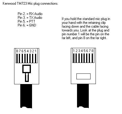
PTT Connection.
Remove the front panel and gain access to the PCB of the control head. You
need to connect a wire from the PTT line of your TNC to the PCB at back of the
MIC connector. Pin 5 of the MIC connector is the PTT.
1200 baud Packet Connection.
For normal 1200 baud packet use, just connect your TNC to the MIC connector,
for all TX and RX audio plus the PTT control.

21-04-2000 TM-732A 2 Meter transmit
interference on 70 CM
Author:
Kenwood Communication, inc.
Service Bulletin no. 996 (20 May 1992)
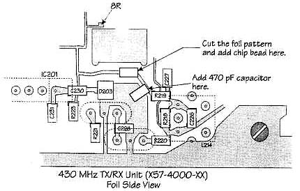
Reports of 70 cm receiver interference might occur when transmission is
attempted on two meters. This is caused by a harmonic relationship that occurs
between 2 meter frequencies and the IF image frequency. The resulting signal
enters IC201 (FM HIC) on the 8R line of the 430 MHz TX/RX unit.
Addition of a chip bead and bypass capacitor on the 8R line will correct this
tendency.
Parts required:
470 pF chip capacitor          CK73FB1H471K
Chip bead                      L92-0131-05
Note: Don't confuse the chip capacitor with the chip bead. They have
the same shape. The chip bead is black and the chip capacitor is brown so it
should be a simple matter to identify the correct part.
Time required for this modification is 30 minutes.

22-04-2000 TM-732A/E Change in chip fuse
rating
Author: Kenwood
Communication, inc.
Service Bulletin no. 1005 (10 May 1993)
Parts change:
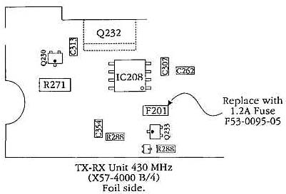
Change the chip fuse from 1 A to 1.2 A in the 430 MHz
unit (X57-4000-11 B/4) whenever servicing this board.
Parts required:
F201, chip fuse, 1.2 Amp, (F53-0095-05), QTY. 1
Caution: This modification requires soldering equipment rated for
CMOS type circuits. It also requires familiarity with surface mount soldering
techniques. If you do not have the proper equipment or knowledge do not attempt
this modification yourself. Seek qualified assistance.
Time required for this modification is 15 minutes or less.

22-04-2000 TM-732A Low cross-band repeater
audio
Author: Kenwood
Communication, inc.
Service Bulletin no. 1011 (3 May 1993)
Symptom:
Improper DTMF operation and low microphone audio have been
reported by several owners of the TM-732A when the units are operated in the
Cross-band repeat mode.
Parts required:
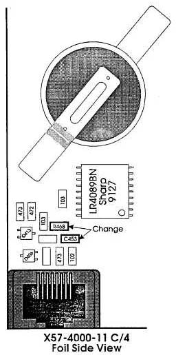
R468    39 Kohm chip resistor     RK73FB2A393J       QTY. 1
C453    .01 µF chip capacitor     CK73FB1E103K       QTY. 1
Procedure:
- Detach the front panel assembly from the chassis.
- Remove the top and bottom covers from the chassis.
- Remove the small countersunk Phillips head screws from the sides of the
chassis. These are used to secure the two brackets that holds the plastic
front cover to the chassis. Gently pull the plastic cover assembly forward and
remove it from the chassis.
- The TX/RX Control unit should now be visible on the front of the chassis
assembly.
- Replace R468 and C453 shown in the accompanying diagram.
- Reverse steps 1 - 3 to reassemble the transceiver.
No additional
adjustment or modification will be required.
 |
Caution: This modification requires soldering
equipment rated for CMOS type circuits. It also requires familiarity with
surface mount soldering techniques. If you do not have the proper
equipment or knowledge do not attempt this modification yourself. Seek
qualified assistance. |
Time required for this
modification is 30 minutes or less.

22-04-2000 TM-732A/E Noise at squelch
ON/OFF
Author: Kenwood
Communication, inc.
Service Bulletin no. 1014 (10 May 1993)
Symptom:
While receiving a signal on one band a noise is heard in
the speaker whenever the squelch on the other band opens or closes.
Correct Action:
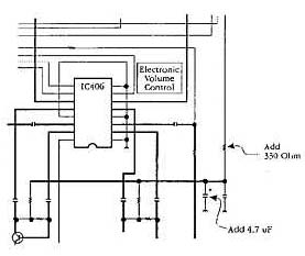
Add a 330 ohm resistor and 4.7 µF capacitor to the
5C line in the control unit (X57-4000-11 C/4). Cut the 5C line and add the 330
ohm resistor in series.
Parts required:
330 ohm resistor      RD14BB2C331J   QTY. 1
4.7 µF capacitor      C92-0507-05    QTY. 1
 |
Caution: This modification requires soldering
equipment rated for CMOS type circuits. It also requires familiarity with
surface mount soldering techniques. If you do not have the proper
equipment or knowledge do not attempt this modification yourself. Seek
qualified assistance. |
Time required for this
modification is 30 minutes or less.

23-04-2000 TM-732A S-meter squelch scan stop
improvement
Author: Kenwood
Communication, inc.
Service Bulletin no. 1023 (26 May 1993)
Symptom:
On some early versions of the TM-732 scan will not stop
when operating in the S-meter squelch mode, even when the transceiver receives a
signal with the same level as specified when initiating the S-meter squelch
mode.
Correct action:
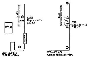
Change the value of C42 in the 144 MHz TX/RX unit
(X57-4000 A/4) and C242 in the 430 MHz TX/RX unit (X57-4000 B/4) from 1 µF to
0.47 µF.
Parts required:
Qty   Description                          Kenwood Part No.  Circuit description
 2    0.47 µF capacitor                    CK73FF1C474Z      C42, C242
 |
Caution: This modification requires soldering equipment
rated for CMOS type circuits. It also requires familiarity with surface
mount soldering techniques. If you do not have the proper equipment
or knowledge do not attempt this modification yourself. Seek qualified
assistance. |
Time required for this modification is
30 minutes or less.

23-04-2000 TM-732A Protection of Q201 in 430
MHz unit
Author: Kenwood
Communication, inc.
Service Bulletin no. 1027 (28 June 1993)
Symptom:
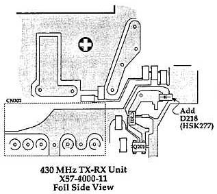
Q201 the first RF amplifier in the 430 MHz unit fails at
random.
Corrective action:
Addition of diode D218 in parallel with diode
D214 in the RA line provides increased surge protection for Q201.
Parts required:
Qty   Description                          Kenwood Part No.  Circuit description
 1    Diode                                HSK277            D218
Caution: This modification requires soldering equipment rated for
CMOS type circuits. It also requires familiarity with surface mount soldering
techniques. If you do not have the proper equipment or knowledge do not
attempt this modification yourself. Seek qualified assistance.
Time required for this modification is 30 minutes or less.

23-04-2000 TM-732A Control PC Board B+ foil
damage
Author: Kenwood
Communication, inc.
Service Bulletin no. 1051 (28 March 1994)
Symptom:
Unable to turn on the power. No DISPLAY illumination,
radio does not function.
Countermeasure:
The B+ circuit foil path near connector CN403 of
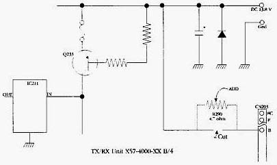
the CONTROL units is burned open. This symptom can occur when the front panel is
unplugged from the main chassis while the power is till turned on. Adding the
resistor shown in series with the "B" line will help to limit current flow and
prevent/limit this symptom from occurring.
Parts required:
Qty   Description                          New Part No.      Circuit Description
 1    4.7 ohm chip resistor                R92-1281-05       R290
Caution: This modification requires soldering equipment rated for
CMOS type circuits. It also requires familiarity with surface mount soldering
techniques. If you do not have the proper equipment or knowledge do not attempt
this modification yourself. Seek qualified assistance from your closest Kenwood
Service Center (Long Beach, CA, or Virginia Beach, VA).
Time required for this modification is 60 minutes or less.

23-04-2000 TM-732A/E APC circuit
improvement
Author: Kenwood
Communication, inc.
Service Bulletin no. 1056 (28 March 1994)
Symptom:
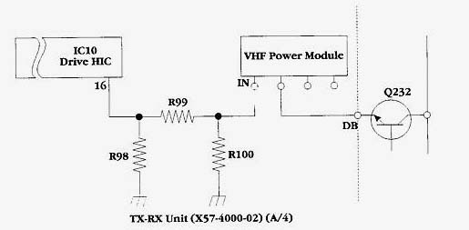
Failure of APC circuit transistor Q232 can occasionally be
attributed to the gain dispersion charcteristic of the VHF power module. Some of
these devices allow normal transmit power output even with reduced "DB" terminal
voltages. If the units is then operated for extended transmit key down periods
Q232 can overheat and fail.
Corrective Action:
- Measure the transmit power output and the "DB" terminal voltage at a dial
frequency of 145.02 MHz.
- Add the 1 dB circuit if the transmitter power is 60 watt or greater and
the "DB" terminal voltage is 10 Vdc or less.
- After adding the attenuator, re-adjust the transmitter output power for 50
watt and check the "DB" voltage. The "DB" voltage should now fall between 10
and 11 Vdc. If it does not adjust the values for R98, R100, and R99 until this
voltage range is obtained.
Parts required:
Qty   Description                          New Part No.      Circuit Description
 *    820 ohm chip resistor                RK73FB2A821J      R98, R100
 *    470 ohm chip resistor                RK73FB2A471J      R98, R100
 *    270 ohm chip resistor                RK73FB2A271J      R98, R100
 *    5.6 ohm chip resistor                RK73FB2A5R6J      R99
 *    10 ohm chip resistor                 RK73FB2A100J      R99
 *    18 ohm chip resistor                 RK73FB2A108J      R99
* Note: Quantities vary depending upon level of attenuation required to meet
requirement of step 3.
| Pad Attenuation
| R98,R100
| R99 |
| 1 dB |
820 ohm |
5.6 ohm |
| 2 dB |
470 ohm |
10 ohm |
| 3 dB |
270 ohm |
18 ohm |
Time required for this modification is 60 minutes or less.


